Atmega328p Microcontroller ADC
It is a simple project using Analog-to-Digital Converter (ADC) on Atmega328p (Arduino UNO), so for this example, it will be used a Sensing Force. The Sensing Force is optimized for use in human touch control of electronic devices such as automotive electronics, medical systems, and in industrial and robotics applications. This project has only two outputs and the outputs depend on the ADC input value.
The Atmega328p DataSheet that will be used to develop the code.
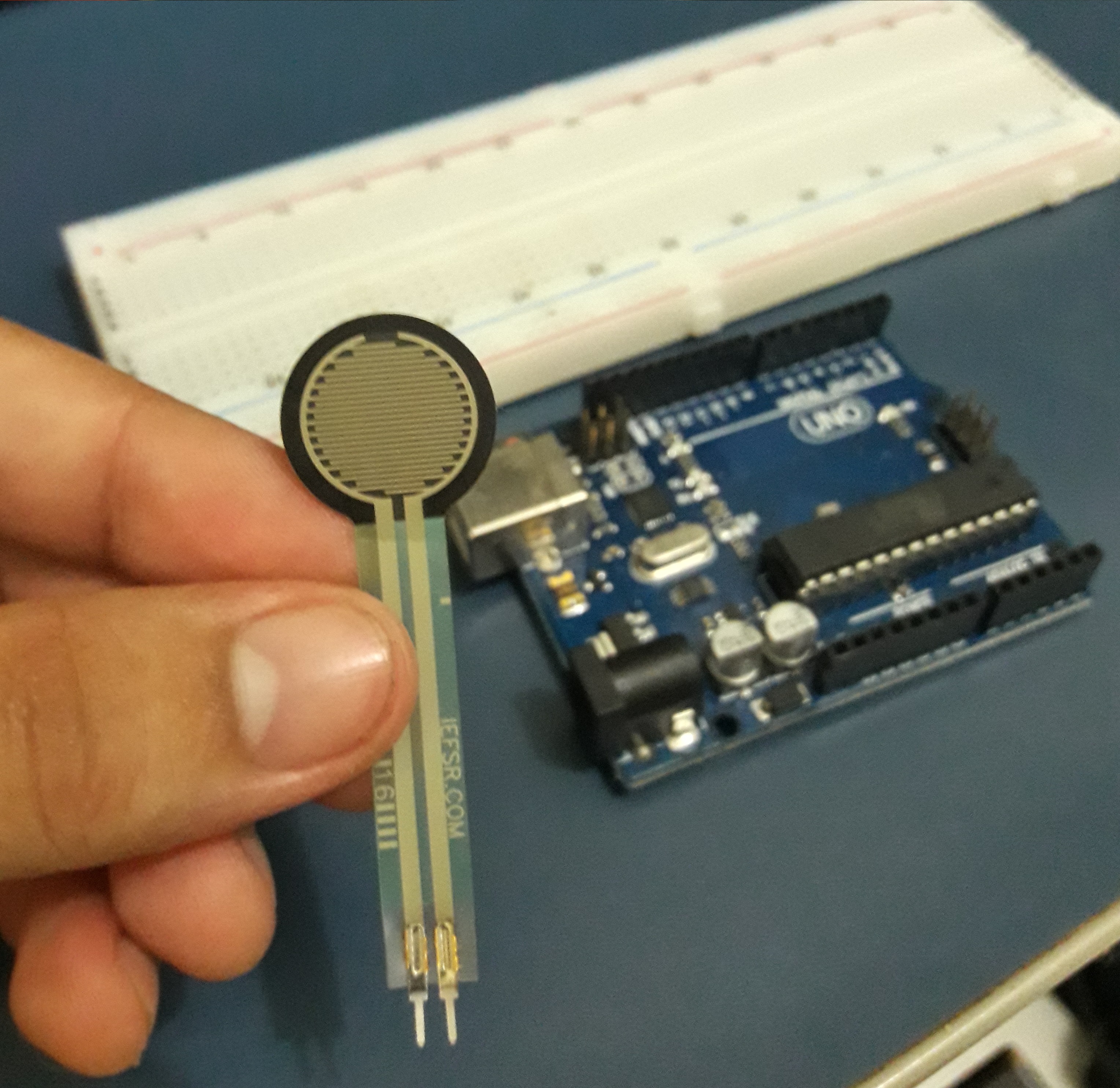
Component - Sensing Force
the component used in this project is the FSR 402 model that is a single-zone Force Sensing Resistor which is a Force Sensing that provides an inverse change in resistance in response to an increase/decrease in applied force.
Code
Initialization ADC function:
The ADMUX register is used to select reference voltage source, how the result should be stored, analog port channel to be used for conversion.
The ADCSRA register is responsible for enabling ADC, start ADC converting, prescaler selection and interrupt control.
void InitADC()
{
	// Select Vref=AVcc (5v)
	ADMUX |= (1<<REFS0);
	//set prescaler to 128 and enable ADC
	ADCSRA |= (1<<ADPS2)|(1<<ADPS1)|(1<<ADPS0)|(1<<ADEN);
}
Read ADC function
Setting the ADSC bit to logic 1 on ADCSRA register tells ADC to start the conversion.
uint16_t ReadADC(uint8_t ADCchannel)
{
	//select ADC channel with safety mask
	ADMUX = (ADMUX & 0xF0) | (ADCchannel & 0x0F);
	//single conversion mode
	ADCSRA |= (1<<ADSC);
	// wait until ADC conversion is complete
	while( ADCSRA & (1<<ADSC) );
	return ADC;
}
Initialization of the Ports
The DDR (Data Direction Register ) registers are responsible for determining whether the pins of a particular PORT will behave as input or output. Each bit of the DDR register controls the state of its respective pin. So it’s setting the Port PC0 (A0) as ADC input and the digital ports PB4(D12) and PB5(D13) as outputs.
	DDRC &= ~(1<<DDC0); //Set PORTC0 as input
	DDRB |= (1<<DDB5);	//Set PORTB5 as output
	DDRB |= (1<<DDB4);	//Set PORTB4 as output

	InitADC();
ADC result and its conditions
this example has two levels of sensitive touch, it can be set as the first level for a less sensitive touch, it will turn on just one LED, and as the second level for stronger sensitive touch, so the two outputs will turn on, therefore both LEDs will turn light on.
There are many others applications, for example, the volume of the car sound can increase slowly on the first sensitive touch level, and the volume of the car sound can increase faster on the second sensitive touch level.
adc_res=ReadADC(0);

		if(adc_res > 1022){
			PORTB |= (1<<PORTB5);  // toggle LED
		}
		if(adc_res > 512){

			PORTB |= (1<<PORTB4); // // toggle LED
		}